ICS Security Solutions for Typical Industrial Scenarios
System Introduction
Based on computers, communication devices, and test control units, the electric power monitoring system provides a basic platform for real-time data collection, switch status monitoring, and remote control of thermal power plants. It can work with detection and controls devices to form an arbitrarily complex monitoring system. It plays a vital role in the monitoring of thermal power plants by helping enterprises eliminate information silos, reduce operating costs, improve production efficiency, and accelerate the speed of responding to anomalies in the process of power transformation and distribution.
The electric power monitoring system of a thermal power plant consists of the distributed control system (DCS) of the thermal power unit, auxiliary control system of the thermal power unit, plant-level supervisory information system (SIS) of the thermal power plant, governor system and automatic generation control (AGC) function, excitation system and automatic voltage control (AVC) function, network control system, the phasor measurement unit (PMU), five-prevention system, telecontrol system, relay protection and fault information substation, and power acquisition unit. The governor system and AGC function, excitation system and AVC function, network control system, relay protection and fault information substation, telecontrol system, and power acquisition unit are power monitoring systems related to the control center; DCS of the thermal power unit, auxiliary control system of the thermal power unit, plant-level SIS of the thermal power plant, and five-prevention system are internal monitoring systems of the power plant; the PMU, relay protection and fault information substation, and power acquisition unit are factory devices of the control center monitoring system. Figure 4.1 shows the architecture of the electric power monitoring system of a thermal power plant.
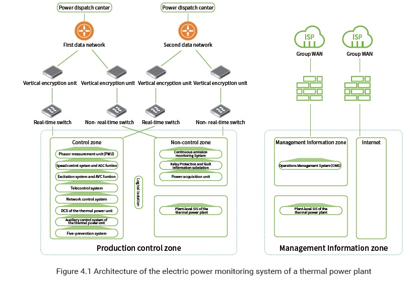
The electric power monitoring system vertically connects to the provincial control center and network control center and is built with the first and second data networks, forming a redundant structure.
System Protection Solutions
Border Protection Solution
- Horizontal border protection
- Horizontal border protection for the production control zone and management information zone
According to actual data interaction requirements of the thermal power plant, forward and backward isolating devices are deployed at the borders of security zone II of the production control zone and the management information zone. Such deployment is to protect the security of forward and backward data flows between the production control zone and management information zone.
Control Zone (Security Zone I) and Non-control Zone (Security Zone II) Border Protection Hardware firewalls are respectively deployed at the network border of the control zone and that of the non-control zone, so as to prevent unauthorized access of systems of a lower security level to systems of a higher security level and provide security guarantee for data flows from security zone II to security zone I.
For cross-zone connections with SIS interface message processors via a serial cable, no firewall can be deployed for logical isolation. In this case, associated SIS interface message processors can be deployed in the control zone (security zone I). If no firewall is deployed between servers and SIS interfaces, industrial control firewalls should be deployed.
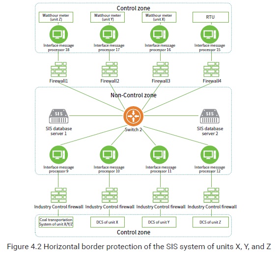
As shown in Figure 4.2, the SIS interface message processors, which connect to watthour meters of units X, Y, and Z, and the RTU respectively, are logically isolated from the switch by four traditional firewalls, while the SIS interface message processors, which connect to the DCSs of units X/Y/Z, X, Y, and Z, are logically isolated from the switch by industrial control firewalls.
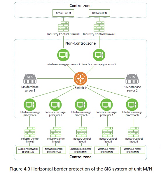
As shown in Figure 4.3, the SIS interface message processors, which connect to the DCS of unit M, DCS of unit N, auxiliary network of unit M/N, network control system (NCS), are logically isolated by industrial control firewalls.
Security protection between systems
According to No.14 Decree of the National Reform and Development Commission (NRDC), all subsystems of the electric power monitoring system should directly adopt the logical isolation technology, such as the VLAN or firewall technology. Each subsystem is logically isolated from other subsystems by using the VLAN technology, so as to meet the requirements for relatively independent connections between subsystems and system availability.
Vertical border protection
Two sets of communication devices, which back up each other, are deployed respectively for the communication between the thermal power plant and the provincial power dispatch center. In addition, two independent vertical encryption devices are deployed between the access switch in security zone I and the egress router of the power dispatch center.
A vertical encryption authentication device is deployed between the thermal power plant and the centralized control center, so as to establish an encrypted tunnel between the plant and the centralized control center. The communication between the centralized control center and plant adopts the double gateway redundancy mode. Both the master fiber channel and backup channel of each communication gateway are equipped with a vertical encryption authentication device.
Third-party protectionÂ
For thermal power enterprises with a third-party border (for example, they may need to communicate with departments of environmental protection), dedicated isolation devices for the power should be deployed for security protection of the same level.
To be continued.