
Container Network Security
-
Network Security Mechanisms
Isolation and access control are two major protection means for computer networks. This section uses host networks in bridge mode and cluster networks in overlay mode as examples to discuss how these security mechanisms are implemented. In general, container networks are isolated by using the network namespace technology and iptables, while access control mainly depends on iptables.
- Network Isolation and Access Control in Bridge Mode
According to Docker’s design principle, in a bridge network, as long as two containers are connected to the same network bridge, they can access[1] each other without any access control or isolation mechanisms. To isolate the two containers from each other, users need to create different bridge networks to house the containers. The detailed process is as follows:
First, create bridge network test:
| # docker network create –subnet 102.102.0.0/24 test
c11c01a07ed0ca3f4cdddee55e3e058e79c334d516b3a49dd3e56b86a4ff9302 Â # ifconfig | grep 102.102.0. -B 1 br-bff064219957 Link encap:Ethernet HWaddr 02:42:69:46:0b:21 inet addr:102.102.0.1 Bcast:102.102.0.255 Mask:255.255.255.0 |
From the preceding command output, you can see that test‘s network bridge is br-bff064219957. After this network is set up, Docker will add DROP rules for the DOCKER-ISOLATION chain in iptables to block bidirectional traffic between test and other networks for the purpose of network isolation.
| # iptables -t filter -L –v
Chain DOCKER-ISOLATION (1 references) pkts bytes target prot opt in                 out        source   destination 0 0 DROP all — docker_gwbridge br-bff064219957 anywhere anywhere 0 0 DROP all — br-bff064219957 docker_gwbridge anywhere anywhere 0 0 DROP all — docker0 br-bff064219957 anywhere anywhere …… |
A zero trust model requires that different containers should not communicate with each other by default. For this purpose, users can set the Docker daemon’s startup parameter, –icc=false, so that packets from the FORWARD chain of the iptables will be dropped by default after the daemon is started. When the Docker daemon runs, users need to add appropriate access control policies that fit in with actual business requirements. For Cloud Workload Protection (CWP), such whitelist-based policies are quite important for deployment of mission-critical business environments as they can minimize the exposure surface and restrict connections of unknown business so as to reduce the likelihood of breach.
| # iptables -nL
Chain FORWARD (policy DROP) DROP all — 0.0.0.0/0 0.0.0.0/0 …… |
The preceding inter-container access control policies can be created manually by using the —link parameter or the docker-compose command when containers are started.
External access to containers on the host is based on such a principle: Container-provided services are accessible via ports that are configured to be exposed to the Internet by using the -p or -P parameter. when and only when containers are started. Arguably, this access control mechanism is specific to hosts, with ports as the granularity of protection.
- Network Isolation and Access Control in Cluster Mode
This section uses Docker Swarm as an example to describe the security mechanism for container networks in cluster mode. Put simply, Docker Swarm’s overlay network complies with IETF VXLAN standards for isolation of different subnets. The following illustrates how the isolation and access control mechanism of Docker Swarm’s overlay network works.
(1) Set up a cluster environment.
Prepare a cluster that contains two nodes.
| # docker node ls
ID HOSTNAME STATUS AVAILABILITY MANAGER STATUS ENGINE VERSION otsycjte53ve20byk79aukwl4 *      node1    Ready    Active Leader 18.03.1-ce icd266rwlmpa47mghng1jvd7b     node2    Ready    Active         17.12.1-ce |
(2) Create two overlay networks.
Create two overlay networks, i.e., test0 and test1.
| # docker network create -d overlay test0
vn86l7s11gfj9ttnzexhgl0yh # docker network create -d overlay test1 w9p3tfmr09c6gw1to0guglfc0 |
| # ls -l /run/docker/netns
total 0 -r–r–r– 1 root root 0 May 28 00:56 1-3cv9ry2rsk -r–r–r– 1 root root 0 Jun 1 14:15 1-vn86l7s11g -r–r–r– 1 root root 0 May 9 19:08 default -r–r–r– 1 root root 0 Jun 1 14:17 1-w9p3tfmr09 -r–r–r– 1 root root 0 May 28 00:56 ingress_sbox …… |
Clearly, Docker creates a namespace for each overlay network. Such namespace names begin with “1-” followed by a string which is the prefix of the overlay network ID. For example, the namespace is 1-vn86l7s11g for test0, 1-w9p3tfmr09 for test1, and 1-3cv9ry2rsk for the ingress network. Note that those namespaces are named differently on different posts.
(3) Create services.
Create services, web0, web1, and web2, of which the former two share test0 and the latter uses test1[2].
| # docker service create –name web0 –network test0 nginx:alpine
ugeorthtdyrf6axaxdigseyru # docker service create –name web1 –network test0 nginx:alpine i4rg9tdkuhv2maf9wzwdkclog # docker service create –name web2 –network test1 nginx:alpine wk34tw25bvdu9zxxdkbsfxv1w |
Set the number of replicas to 3 for web0 and 1 for web 1 and web2 respectively. The cluster topology is shown in the following figure:
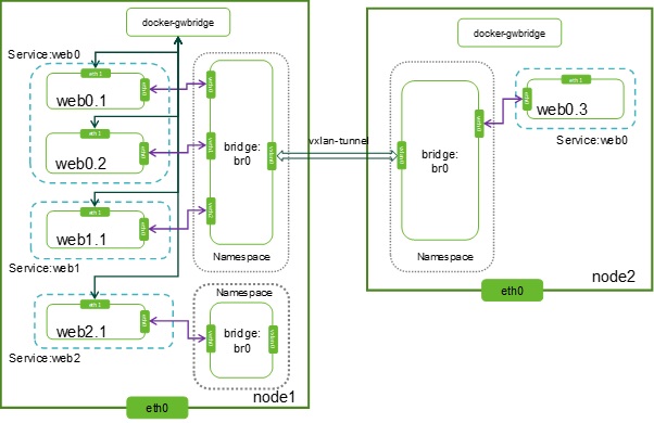
Figure Swarm cluster topology
As shown in the preceding figure, web0.1, web0.2, and web0.3 are container replicas of web0; web1.1 and web2.1 are container replicas created respectively for web1 and web2. web0.1 is the short form of web0.1.u800qsqymguo9avo72w2o3ci0. For the sake of simplicity, suffixes of container instance names are completely removed in subsequent sections.
After the environment is set up, you can, based on services, find the network to which containers connect. Take web0 as an example.
| # docker service inspect web0
… “VirtualIPs”: [                {                    “NetworkID”: ” vn86l7s11gfj9ttnzexhgl0yh “,                    “Addr”: “10.0.0.10/24”                }            ] … |
From the above, we can see that this service connects to the test0 network. At least, container replicas of this service also connect to this network. If this service is provided externally, it will connect to the ingress network. For example, querying the test0 network, we can find the server to which the service is connected.
| # docker network inspect test0
[ Â Â Â { Â Â Â Â Â Â Â “Name”: “test0”, Â Â Â Â Â Â Â “Id”: “vn86l7s11gfj9ttnzexhgl0yh”, Â Â Â Â Â Â Â “IPAM”: { Â Â Â Â Â Â Â Â Â Â Â “Driver”: “default”, Â Â Â Â Â Â Â Â Â Â Â “Options”: null, Â Â Â Â Â Â Â Â Â Â Â “Config”: [ Â Â Â Â Â Â Â Â Â Â Â Â Â Â Â { Â Â Â Â Â Â Â Â Â Â Â Â Â Â Â Â Â Â Â “Subnet”: “10.0.0.0/24”, Â Â Â Â Â Â Â Â Â Â Â Â Â Â Â Â Â Â Â “Gateway”: “10.0.0.1” Â Â Â Â Â Â Â Â Â Â Â Â Â Â Â } Â Â Â Â Â Â Â Â Â Â Â ] Â Â Â Â Â Â Â }, Â Â Â Â Â Â Â Â Â Â Â Â Â Â “Containers”: { Â Â Â Â “759bbdf216d801615ff90578dd5a828e53449990a9016b82fdee1689cb7d448f”: { Â Â Â Â Â Â Â Â Â Â Â Â Â Â Â “Name”: ” web0.1.u800qsqymguo9avo72w2o3ci0″, Â Â Â Â Â Â Â Â Â Â Â Â Â Â Â “EndpointID”: “b03c9a96d81d91301594951fcc08ec0765102b37810c77ec8cb4943bda4e9868”, Â Â Â Â Â Â Â Â Â Â Â Â Â Â Â “MacAddress”: “02:42:0a:00:00:06”, Â Â Â Â Â Â Â Â Â Â Â Â Â Â Â “IPv4Address”: “10.0.0.6/24”, Â Â Â Â Â Â Â Â Â Â Â }, Â Â Â Â Â Â Â Â Â Â Â “791de588518714ae1b3140956918c5d5adcae151f10ef3c9b5808ff0638ab357”: { Â Â Â Â Â Â Â Â Â Â Â Â Â Â Â “Name”: “web0.1.n9pjx00w99fiwqch01gaiew90”, Â Â Â Â Â Â Â Â Â Â Â Â Â Â Â “EndpointID”: “8bfbb44db8e81734676d4756d7152a5ea3f57d7aae987600e238b5a70c15d670”, Â Â Â Â Â Â Â Â Â Â Â Â Â Â Â “MacAddress”: “02:42:0a:00:00:04”, Â Â Â Â Â Â Â Â Â Â Â Â Â Â Â “IPv4Address”: “10.0.0.4/24”, Â Â Â Â Â Â Â Â Â Â Â }, Â Â Â Â Â Â Â Â Â Â Â “e6c02f73a9c72d23fcd5c17aa265adf1de56d1c933f396e6995b066c0b333f11”: { Â Â Â Â Â Â Â Â Â Â Â Â Â Â Â “Name”: “web0.3.rmmfijc7jmr8grld6pwkm5e0q”, Â Â Â Â Â Â Â Â Â Â Â Â Â Â Â “EndpointID”: “d223943dc20da5c57bcd19d9f2b743cd59cad00b6a84eae44048937ef3780324”, Â Â Â Â Â Â Â Â Â Â Â Â Â Â Â “MacAddress”: “02:42:0a:00:00:05”, Â Â Â Â Â Â Â Â Â Â Â Â Â Â Â “IPv4Address”: “10.0.0.5/24”, Â Â Â Â Â Â Â Â Â Â Â }, Â Â Â Â Â Â Â Â Â Â Â “e9fc84b0d736107cec501436d08d4911dd4a516bfcce3e5b95016913ff2b8521”: { Â Â Â Â Â Â Â Â Â Â Â Â Â Â Â “Name”: “web1.1.6f9chzfd711nmjenc6bgg109x”, Â Â Â Â Â Â Â Â Â Â Â Â Â Â Â “EndpointID”: “703622e4d0cd0ceca52c6b10a2c5451e6767845147625a21d18a7cf99b7cef56”, Â Â Â Â Â Â Â Â Â Â Â Â Â Â Â “MacAddress”: “02:42:0a:00:00:07”, Â Â Â Â Â Â Â Â Â Â Â Â Â Â Â “IPv4Address”: “10.0.0.12/24”, Â Â Â Â Â Â Â Â Â Â Â } Â Â Â Â Â Â Â }, Â Â Â Â Â Â Â Â Â Â Â Â Â Â “Peers”: [ Â Â Â Â Â Â Â Â Â Â Â { Â Â Â Â Â Â Â Â Â Â Â Â Â Â Â “Name”: “17a9fb8e9cd2”, Â Â Â Â Â Â Â Â Â Â Â Â Â Â Â “IP”: “192.168.19.11” Â Â Â Â Â Â Â Â Â Â Â }, { Â Â Â Â Â Â Â Â Â Â Â Â Â Â Â “Name”: “5a56d8c9a2b6”, Â Â Â Â Â Â Â Â Â Â Â Â Â Â Â “IP”: “192.168.19.12” Â Â Â Â Â Â Â Â Â Â Â } Â Â Â Â Â Â Â ] Â Â Â } ] |
It is clear that a VXLAN tunnel is set up between Docker Swarm and the host. The above test0 network information shows that on top of the underlay network comprising two hosts, 192.168.19.11 and 192.168.19.12, an overlay subnet, 10.0.0.0/24, is built, with the network gateway address of 10.0.0.1 (network address of br0 of the namespace 1-vn86l7s11g).
In addition, when both web0 and web1 connect to test0, their container replicas also connect to this network. As network interfaces in the namespace of test0 have no VLAN IDs, no VLAN is set for these interfaces on the network bridge and containers on one host in the same network can access on another without any isolation measures.
| # s1-vn86l7s11g bridge vlan
port vlan ids br0Â Â Â Â Â Â Â Â None vxlan0Â Â Â Â None veth0Â Â Â Â Â Â None veth1Â Â Â Â Â Â None # nsenter –net=/var/run/docker/netns/1-vn86l7s11gbridge fdb show dev vxlan0 22:71:ed:59:a9:59 master br0 permanent 02:42:0a:00:01:09 dst 192.168.19.12 link-netnsid 0 self permanent 02:42:0a:00:01:08 dst 192.168.19.12 link-netnsid 0 self permanent 02:42:0a:00:01:06 dst 192.168.19.12 link-netnsid 0 self permanent |
On computing nodes in OpenStack, different VLANs are set to isolate subnets of different tenants on the network bridge connected to the VXLAN tunnel. In contrast, in Docker Swarm as shown above, networks are isolated by using network namespaces, instead of VLANs.
For example, container replicas of web0 connect to the test0 network. This means that packets, which arrive from containers to the network bridge br0 of the namespace 1-vn86l7s11g, can only be sent to other container replicas (containers connected to br0 in the 1-vn86l7s11g namespace of this host or other hosts) that are connected to the test0 network, instead of containers connected to the test1 network. This can be verified as follows:
| # docker exec web0.1 ping 10.0.0.12Â -c 1
PING 10.0.0.12 (10.0.0.12): 56 data bytes 64 bytes from 10.0.0.12: seq=0 ttl=64 time=0.250 ms — 10.0.0.12 ping statistics — 1 packets transmitted, 1 packets received, 0% packet loss round-trip min/avg/max = 0.194/0.194/0.194ms  docker exec web0.1 ping 10.0.1.5 -c 4 PING 10.0.1.5 (10.0.1.5): 56 data bytes — 10.0.1.5 ping statistics — 4 packets transmitted, 0 packets received, 100% packet loss |
(4) Control access to containers in a cluster.
As previously mentioned, in Docker Swarm, containers in the same overlay network can access one another by default, while those in different overlay networks cannot. There are no customizable access control policies for containers. If access control policies need to be applied explicitly, users need to create them manually.
Now, we create a service exposed to the external network:
| # docker service create –name web5 –network test1 –replicas 3 -p 3000:80 nginx:alpine
c3ql2e1e0g7xbxksfz3pjlrgb |
As the -p parameter is selected during service creation, four network interfaces will be created for containers of this service.
The eth0 interface connects to the ingress network which acts as an intermediary between external networks and containers.
The eth1 interface connects to the docker_gwbridge network. This network provides the communication from containers to an external network. For example, when the ping www.baidu.com command is executed in a container, the traffic will go through the default_gwbridge network.
The eth2 interface connects to the test1 network for communications between container replicas across host services.
This service is available on port 3000 exposed externally, while the container listens on port 80. External access to port 3000 is achieved through port mapping.
| # iptables -t nat -n -L | grep -A 4 ‘DOCKER-INGRESS’
— Chain DOCKER-INGRESS (2 references) target prot opt source destination DNAT tcp — 0.0.0.0/0 0.0.0.0/0 tcp dpt:3000 to:172.17.0.2:3000 RETURN all — 0.0.0.0/0 0.0.0.0/0 |
Passing through the iptables of the host, the packet arrives at the namespace ingress_sbox after going through the network bridge docker_gwbridge. After IPVS load balancing, the destination IP address will be translated into the IP address of the container for which the packet is destined when being transmitted in the ingress network.
It can be seen that to control external access to the service, access control rules can be deployed for data channels between the eth0 interface on the host and the destination container. For example, create access control lists (ACLs) for the DOCKER-INGRESS chain in the iptables table or deploy a firewall outside the host. Of course, whichever method is used, access control rules should be adjusted in light of changes to containers. This requires full integration between the access control management mechanism and the container orchestration system. The following figure shows the external access to port 3000 on node1 and node2. Arrows in green and orange indicate the entire process of packets passing through different host ports to the Web5.3 container.
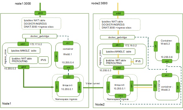
Figure 4.2 Cluster data transmission process of Docker Swarm
- Micro-segmentation
Service software’s transition from individual applications to a lot of container-based microservices brings many benefits and also changes the internal communication mode of software. As for network and security, two noticeable changes are observed: 1. The communication traffic surges horizontally. 2. Borders become much more blurred. Even if each running container can be hardened and a limit can be set on the number of interfaces for external communication, as the total number of interfaces increases dramatically, more opportunities are opened up for network attackers to detect vulnerabilities.
Besides, containers can be rapidly deployed within seconds. The container orchestration system can automatically start new containers on one or more hosts according to the actual resource situation. Each container has its own network mapping interface which can be reallocated and unbound in the course of running, especially because containers have a very short lifecycle, with 17% lasting less than one minute and 78% disappearing within an hour[i]. Therefore, container protection should be agile and elastic.
In a dynamically changing container environment, traditional network firewalls could hardly detect any inter-container network traffic and also cannot adapt to the constantly changing situation as containers start and disappear rapidly. As one cybersecurity architect said, “In a containerized world, you can never manually configure iptables or update firewall rules.”
Given all above analysis, in a cloud-native environment, cloud-native container firewalls are required to isolate and protect application containers and services. Even if containers dynamically expand or shrink, such firewalls can still detect, track, and protect them. Like traditional gateway firewalls, container firewalls can also protect network communication that is from external networks and traditional applications to the container environment.

Figure 4.3 Container firewall in micro-segmentation
Micro-segmentation is a kind of segmentation technology which is more fine-grained than traditional segmentation based on network addresses. For example, this technology can implement isolation and segmentation for individual containers, container collections or container applications in the same network segment. With micro-segmentation as an essential feature, container firewalls can perceive layer 7 or the application layer and provide dynamic control of connections, depending on upper-layer applications. We can see that this kind of firewalls implements dynamic micro-segmentation for services and therefore has become the first line of defense to protect containers in horizontal traffic scenarios from malicious attacks.
Container firewalls mainly protect inter-container network sessions in horizontal scenarios, and thus will not replace protective systems, like NGFW, IDS/IPS, and WAF, deployed at the entrance of the data center. On the contrary, container firewalls, through collaboration with those traditional firewalls, can effectively block attacks that are initiated from internal applications.
-
Security Protection for the Container Network
- Web Application Security
Typically, external microservices take the form of web or HTTP applications and services, for example, websites or applications with support for REST APIs. For the sake of security, you can deploy web applications to detect and block malicious HTTP requests. This section describes how to perform cybersecurity protection for web applications. For the security of other applications, see the threat detection section.
Microservices can receive traffic from vertical and horizontal directions. Take node1 as an example. As shown in the following figure, the traffic from the external network to the Web5 service is vertical. To protect the traffic, you can deploy a web application firewall on the external network.
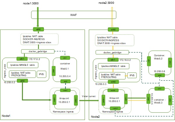
Example for vertical traffic protection of web applications
The container environment also contains a great number of API calls, or even you might say that the traffic of a data center mainly comprises invocation requests and responses of such APIs. Such traffic is called horizontal traffic. To protect the traffic, you need to deploy virtual web application firewalls (vWAF or cWAF) in the internal network of a host. As the container management and orchestration system will create or delete container instances dynamically according to actual business requirements, it needs to connect to the container management and control plane and has vWAF deployed to track dynamic network changes.
Take node1 as an example. Web5 connects to the 10.255.0.0/24 and 172.17.0.0/24 networks. Therefore, for protection of Web5’s container replica (Web5.1 in the following figure) on the node1 host, you can deploy a vWAF respectively at the network bridge docker_gwbridge and the network bridge br0 in the namespace ingress. In this case, vWAF, in out-of-path mode, can detect malicious requests by mirroring traffic, and in in-path mode, can filter traffic for protection.
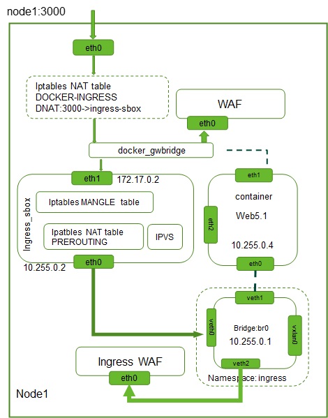
Example for horizontal traffic protection of web applications
The software-defined networking (SDN) technology can be introduced to implement flexible traffic scheduling so that fewer WAFs need to be deployed for intended security protection. For details, see the 2015 NSFOCUS SDS White Paper[ii].
- Network Security Protection
Each host and server have a container firewall deployed to gain full access to the local Docker daemon. As the container firewall resides within the container network, it can easily detect abnormal behaviors on the container network, especially horizontal inter-container movements of malicious attackers. Also, a machine learning module can be integrated in the container firewall to automatically learn security policies for effective container security protection.
Deployed in a distributed manner, a container firewall can provide effective local monitoring and protection. Seamlessly integrating with the Docker engine and container orchestration management tools, the container firewall, besides access control, can also provide security audit, security testing, resource monitoring for hosts and containers, and the like. From this point of view, the container firewall is essentially a security policy strengthening point in the container network, rather than the traditional firewall in the narrow sense. This security policy strengthening point provides the following functions:
- Deep inspection of and visibility into container network communications to gain accurate application knowledge for container protection.
- Host process monitoring, process privilege escalation monitoring, and suspicious process detection.
- Static scanning or dynamic real-time vulnerability scanning, image repository scanning, host scanning, and vulnerability scanning for running containers.
- Container audit based on CIS’s security baselines.
- Capture of raw packets of containers for forensics and debugging.
To ensure that containers can be deployed and operate in a secure way, container firewalls should be able to support virtual workloads, automatically learn behaviors of applications, generate smart security policies, and seamlessly integrate with the container orchestration platform.
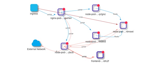
Figure 4.6 Detection and visibility into container network communication
When containers operate, the network security detection engine needs to detect the following items:
- Unauthorized network connections
- Trusted IPs/ports used in an unauthorized manner
- Known cyberattacks against applications
- Data theft, reverse shell channels, and hidden network pipelines
- Container process privilege escalation and malicious processes within containers and the container host
- Unauthorized network ingress/egress control
(To be continued)
[1]The default startup parameter setting of the Docker daemon, –icc=true, indicates that the inter-container communication is allowed by default.
[2]In addition to the loopback interface, containers for the new services provide another two network interfaces, eth0 and eth1. The eth0 interface connects to the network bridge interface of the overlay network test0 or test 1 for inter-container communication across different hosts on the same network. The eth1 interface connects to the docker-gwbridge bridge network for the communication between containers and the host. If –internal is used during the creation of the overlay network, containers for services created with the docker service create –network command, besides the loopback interface, have only the eth0 interface which connects to the network bridge interface of the created overlay network.
[i] 2018 Docker Usage Report, https://sysdig.com/blog/2018-docker-usage-report/
[ii] 2015 NSFOCUS SDS White Paper, http://blog.nsfocus.net/software-defined-security-whitepaper/